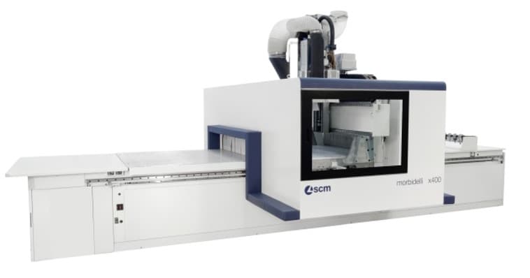
Morbidelli X200 4 X 8 CNC Machining Center
This item may incur additional shipping costs and lead times.
Product Details
The new generation of Nesting CNC machining centres meets the needs of a market increasingly oriented towards flexible and batch-1 production, combining excellent performance, maximum configurability with increased flexibility and productivity.
Every detail is designed to make any performance accessible, leading to efficiency, quality and business evolution.
Advantages
NOT ONLY NESTING: FLEXIBLE: Any machining process without removing the spoilboard and even in 3D thanks to the X-PODs and the JQX (Just Quality eXtreme) 5-axis electrospindle.
FASTER THAN ANY OTHER MACHINE: Nesting processing at 50 m/min, saves 60% of time on drilling cycles thanks to the new drilling heads (also with double saw blade) and less than 15” for the tool change thanks to the FAST tool changer directly installed on the mobile unit.
MAXIMUM HOLDING: TOP QUALITY Thanks to the X-Vacuum System, the vacuum is condensed into the area of the worktable where the workpiece is being processed. Perfect to process small workpieces or highly breathable materials.
HIGHLY MODULAR The ultimate solution to simplify work: cell version, available to configure the machine no matter the material flow required.
Machine Configuration
The bottom supporting structure has been designed to be assembled in a cage-like shape, with all the parts electro welded one and strongly ribbed one to the other so the reach the best rigidity possible; the structure, with a very wide base, grants long lasting stability and precision under all working conditions and doesn’t require the machine being fixed to the ground.
The cage-shaped bottom structure also provides a solid support for the mobile unit on top of it: the operating units moving on the cantilever support take advantage of this balanced base thus granting the highest performances in quality and precision.
The mobile unit, cage-shaped and ribbed, is anchored to the base through a pattern of sliding supports moving on recirculating balls circuits on prismatic guides: this solution grants the best durability along the entire operating life of the machine.
The displacement of the mobile unit along the bottom frame (X axis) and the operating units along the mobile unit’s beam (Y axis) is granted through a rack/pinion system designed with helical teeth so to allow higher thrust tooth-to-tooth thus allowing better acceleration and speed along both X and Y axis.
Helical teeth once properly designed are able to reduce also wear on mechanical organs and noise in operating conditions.
The vertical Z axis is driven through a recirculating balls screw which ensures perfect balance under dynamic loads and bears very high acceleration and deceleration values.
The routing unit is directly installed on the Z-axis slide thus granting the highest finishing quality thanks to a complete absence of vibrations.
The displacements along X-Y-Z axes are managed through "brushless" motors driven by static inverters which grant:
- Reduced cycle timing thanks to higher accelerations
- Better positioning precision through high resolution encoders
- No set-up operations once switching on the machine thanks to absolute encoders utilization
- No general maintenance operations thanks to the absence of brushes, "brushless" system
The management of the axes displacement and generally the devices of the machine is assured by an industrial NC module with digital data transmission carried out through “CAN OPEN BUS” technology, able not only to reach the highest speed in communication intervals but also to be unaffected by external electromagnetic interferences.
PRO-SPACE Safety System
The absence of fences surrounding the machine allows the operator easy access to the working table from any position around the machine with no need to wait for the program interruption. The maximum speed of the axes is limited by the software to 25 m/min (984 in/min), fulfilling current safety norms. This arrangement grants the operator to work in total safety.
The Pro-Space system allows the machine to take a small sized footprint. Thanks to the exclusive solution of integrating the electrical cabinet and the vacuum pump inside the frame structure, SCM can install the machine even in the smallest shops while avoiding repositioning of any equipment
Rear Inspection Opening with RFID Detection Device
Located on the rear left corner of the protective cage, this opening is equipped with a transparent ejection-proof material. Swinging on hinges, it allows for easy maintenance operations on rear side of the machine
Retractable Safety Strip Curtains
Impact-tested multi-layer curtains increase safety around the equipment by providing an added barrier between the operator and the tool in the case of a fracture during machining. The safety strip curtains are equipped with ON-OFF pneumatic vertical movement. It is possible to program the lifting action during the X axis rapid movements. This reduces the impact between work piece and curtain in case delicate panels are present.
Electrical Connection with Voltages Other than 380/400V - 50/60Hz
The machine is equipped with an autotransformer to convert the voltage coming from the main electrical supply to the voltage required to make the machine operative. Instructions for correct electrical connections to the customer power grid are included in the document 90L0635760A which is provided with the machine.
The transformer/auto transformer is ALWAYS:
1) NOT regarded as part of the standard machine supply, but must be integrated in the electrical equipment of the customer’s company
2) NOT connected to the machine by the manufacturer
3) Connected and checked BY THE CUSTOMER
- The autotransformer includes the connection of the neutral for generating 220V inside the electric panel
- Allowed electricity supply networks: TN-S / TN-C
Air Conditioning on Electrical Cabinet
The conditioner maintains a temperature inside the electrical cabinet within the values of a correct machine use. This option is advisable in environments with temperatures above 35°C.
Centralized Air Conveyor
Air conveyor which groups all the machine exhaust outlets and allows to connect it to the general dust collector system through one main exhaust outlet. Inside the main dust collector are fitted pneumatic cylinders that automatically control the opening/closing of each exhaust outlet when the operating unit is switched on/off.
High Efficiency (HE) Multifunction Aluminum Worktable
Includes an aluminum table with vacuum holes set at 120 mm pitch. Closure of the holes is performed by way of a "patent pending" rapid magnetic plug system. Grooves are set at 20 mm from each other for fixing of the workpiece using rubbers gasket. The worktable has been designed for practical and safe use with any device and, most of all, for quick and easy configuration during daily operations.
Built with inert material and immune to the main deformation factors, the table allows - through a 20x20mm grooves grid – for the operator to always find the optimal path to place the rubber gasket. The specific design of the grooves grid also allows placing vacuum pods of varying sizes in any position on the whole worktable which makes the machine suitable for machining operations which require the single part to be raised from the table (horizontal drilling, bottom edge rounding, bottom side machining etc.).
The worktable contains a 120x120mm grid of vacuum outlets which can be opened and closed through metal "plugs". A magnetic insert on each outlet ensures quick management of the vacuum configuration, saving time while setting up the machine and allowing the vacuum power to be distributed only where necessary.
The worktable can be configured with aluminum reference stops on its four corners according to the customer’s requirement. The machine is capable to be configured to process both large and small sized parts with no difficulties for the operator. A rich choice of accessories and configurations makes the machine capable of processing the widest array of pieces. The customer can fulfill any type of requirement coming from the market.
The division of the worktable into multiple vacuum areas is recommended for processing of panels with dimensions which are smaller than the entire worktable. The individual areas are chosen manually by the operator using an information system which allows the areas to be opened or closed. The operator also has the possibility to activate an automatism, where the machine autonomously selects the vacuum area(s) containing the dimensions of the piece.
Worktable Divided in 6 Vacuum Areas (12xx
The perfect solution for small-sized offcuts machining. The minimum surface connected to the vacuum approximately corresponds to:
- X = 1/2 of the working area
- Y = 1/3 of the working area
Manual or automatic selection of the areas according to work piece dimension. For machines with aluminum worktable.
Peripheral Working Areas
Each working area consists of one (1) reference stop on the side (left or right dependent on the area) with 90mm vertical stroke. According to the frame size the stops along the X direction can vary in quantity:
- Worktable xx24 = Three (3)
- Worktable xx31 and xx36 = Four (4)
- Worktable xx43 = Five (5)
Each stop has a vertical stroke of 30mm and contains an M6 female thread on top to install optional pin height extenders.
A single area allows the machining of a single piece at a time. The stops can be activated from the control console.
Rear External Area - LEFT - "A"
Standard work area on the multifunction aluminum worktable.
Rear External Area - RIGHT - "D"
This is an additional work area on the rear of the worktable.
Front External Areas - LEFT and RIGHT - "E" and "H"
Consists of two (2) additional work areas on the front of the worktable.
HITECO Electrospindle 14kW - 19 Hp
Vertical electrospindle equipped on a cast aluminum support, sliding on linear recirculating ball bearings (NC managed).
Technical data:
- HSK 63F attachment with double referencing surface to ensure a rigid connection between the tool-holder and the electro spindle itself.
- Electronic rotation control on speed, from 1,500 to 24,000 rpm through static inverter, quick-stop function on rotation standardly equipped.
- Constant power rate (S1/S6) 10/14 kW (13.6/19 HP) from 12,000 to 18,000 rpm
- Programmable left and right rotation
- Inner air blowing system to guarantee a proper fitting with tool-holder.
- Cooling system through forced air ventilation circuit and fan
- Ceramic bearings as support on the main shaft
- Compressed air circuit inside the router cage as prevention against dust pollution
Dust Extraction Outlet for 3-4 Axis Electrospindle
Automatic ON-OFF positioning and manual stroke adjustment on 4 levels.
Pre-arrangement for HITECO Aggregates with 1 Pneumatic Outlet
It allows the installation of the angle-driven heads on electrospindle, with HITECO with pneumatic outlet fixed mechanical coupling system for the management of special heads like the floating heads.
Variable Cut-off Behavior for Electrospindle
This novel system is used to adjust the cutting speed of the machine’s electrospindle according to the strain made by the tool on the panel. If the CNC detects an overage due to high load on the electrospindle the system will automatically reduce the feed rate of the axes until the load is restored to within acceptable limits.
Air Blowers on the Electrospindle
Four (4) air blowers capable to convey the chips produced by the cutter during machining. This facilitates the chip ejection.
Tool Length Detection Device
This electromechanical device located on the side of the machine frame can detect the tool length through a dedicated software cycle.
The measured length will be sent to the Numerical Control which automatically updates the tool database. This tool database is reviewed by the NC during the loading of any program containing tool compensation into the operator interface.
It is recommended that end users exercise parametric programming to take full advantage of this powerful feature
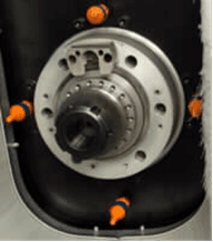
RO.AX F16V Drilling Head
The drilling unit is equipped with new roto-axial technology, Ro.Ax.
Entirely developed by SCM Group, this project grants:
- Improved cutting quality thanks to the increased rigidity of the spindle (enlarged diameter of the rotating shaft and direct connection, no mechanical interfaces between drilling bit and the shaft itself thanks to Weldon attachment type).
- Increased production rate thanks to a maximum rotation regime up to 8,000 rpm (with optional inverter) which allows a higher penetration speed into the material.
- Reduced maintenance interventions (up to 1,000 hours with lubricating mechanical organs on the unit)
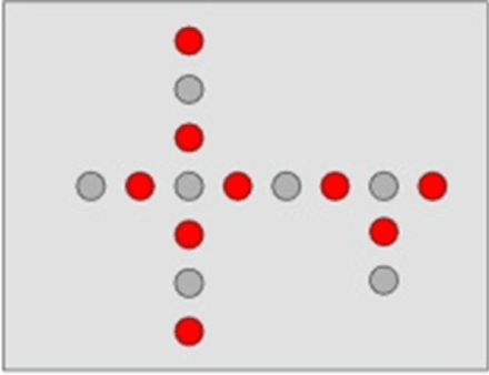
Drilling unit includes:
- Sixteen (16) vertical spindles with independent pneumatic selection
- Bits attachment on vertical and horizontal spindles Ø 10mm, WELDON type (max. length of the bits 70mm)
- Center-to-center step 32 mm between adjacent spindles
- Rotation speed on drilling bits 4,200 rpm (2,500 to 8,000 rpm with optional inverter)
- Driving motor power rate up to 3,9 kW (5,3 HP) – [2,2 kW (3 HP) with 50 Hz frequency]
- 60mm on-off pneumatic stroke on vertical spindles and blade
- Locking system on drilling bit “quarter-lock” type which allows assembling/disassembling tools using single M8 screw and 90° rotation on the wrench.
- Compressed air circuit with high pressure to grant more than 64 kgf thrust on each drilling spindle so to perform operations on the most resistant materials.
Dust Extraction Hood for Drilling Head
Positioned around whole perimeter.
Device to Increase the Drilling Pressure
This device is used for drilling support for the Z-Axis (only on drilling head). It provides Ro.Ax. spindles with an increased thrust during machining, exceeding 64 kg. Each spindle grants full performance on the hardest materials that can be run.
Drilling Unit Managed by Inverter
The inverter managing the rotation speed on the router is also connected to the driving motor on the drilling unit to allow for adjusting the rotation speed of bits up to 8,000 rpm and up to 10,000 rpm on the integrated saw blade.
FAST-12 Twelve (12) Positions Linear Tool Changer (12xx)
Contains a total of 12 positions for HSK tool holders.
The FAST tool changer grants superior performance in tool changing operations. The short distance from the router to the tools, as well as dedicated software optimization, allow for decreased wait time while tool changes are performed.
The FAST-12 is located inside the protective cage on the mobile bridge and can host tools and/or angular heads (please refer to admitted dimensional limits reported in the user manual).
The steel frame construction grants the highest rigidity possible for cases when heavier tools are equipped on it. The tool holder grippers are constructed of a plastic composite material and mounted in an aluminum plate to provide an ideal balance between rigidity and flexibility during tools loading/unloading operations.
The rake and the tool-holders are properly protected against dust by a protective covering over top.
Technical data
- Max. tool diameter: 160mm
- Distance between adjacent positions: min. 125mm
- Max. weight for each tool: 8Kg
- Max. total weight: 42Kg
- Max. weight for each head: 10Kg
Loading Station for FAST Tool Changer
This device - when TRB tool changer is not installed on the machine frame – is used for automatically and easily equipping the FAST tool changer with tools.
It is positioned within the machine frame when not in use
ON-OFF Workpieces Outfeed Pusher
Automatic unloading device which allows the following operations:
- Unloading of the worked pieces on the table side
- Direct positioning on the spoil board
- Spoil board cleaning by means of integrated suction and blower
It consists of a rigid rake (pusher) which touches the spoil board when enabled so to avoid any adjustment once switching to different panel thickness. Additional features:
- Allows the mobile unit to properly push the cut parts – even thin ones – towards the offloading station
- Dust and chips on the spoil board are properly evacuated (best hold down action, no discarded parts, and maximum safety on any successive panel) thanks to the adoption of blowers and a suction hood on the rake itself. The aspiration system is directly connected to the main dust extraction manifold on the machine, avoiding additional tubes on the aspiration system.
The operator gets the best flexibility of usage thanks the ability to associate the outfeed pusher with one of these devices:
- Automatic motorized outfeed belt (optional for a quick panel replacement on the worktable, no operator required to collect the parts during the unloading operation)
- Manual offloading with pushbutton command (optional for a space saving solution, operator required to collect part by part during the unloading operation)
Lower Dust Extraction Grid Between Worktable and Outfeed
Grated stainless steel hood with dedicated connection for suction, able to intercept dust and small chips laying between the processed parts while being offloaded.
Characteristics:
- Exhaust outlet diameter = 200mm
- Exhaust air consumption = 2800 m³/h
- Air speed = 25 m/sec
- Automatic opening valve
- Aspiration tube on bottom position
Control Panel on the Unloading Table
Outfeed table with extension and controls, positioned on the right and left side. The system detects the workpieces by means of photocells to stop the unloading cycle. The processed workpieces can be unloaded through the pressure of the relevant pushbutton.
Side Fences on the Worktable
Fences consist of two (2) pneumatic devices which restrict the ejection of pieces out of the worktable during the automatic offloading phase. This optional is strongly suggested once the machine is equipped as an automated nesting cell. Fences are not suitable to use as front/rear references.
- Fences vertical on-off stroke = 25m
Vacuum Pumps Positioning
Basic machine cell models:
- The vacuum pumps are always located on the base left side, in the area below the unloading belt, even if the belt isn't present
- Basic machine models without automation:
- With 15xx, 18xx, 22xx models and Rotary Vane vacuum pumps it is possible to accommodate up to 2 vacuum pumps below the machine base
- When the Sav€nergy is present, the vacuum pump is always positioned on the base left side
- When the number of pumps exceeds the quantity that can be installed under the base, they will always be positioned outside the base
Two (2) Vacuum Pumps for Total 600 m3/h 60 Hz
The vacuum hold-down system features two (2) 300 cubic meter/hour vacuum pumps. It offers the reliability of a substantial increase in vacuum power and allows the use of spoil boards for nesting full sheets.
Automatic Centralized Lubrication
The correct grease application on the machine’s moving parts is always maintained by means of an electronic control (X-Y-Z axes). The NC managed grease pump ensures that mechanical components on displacement axes (sliding supports, racks, pinions, recirculating ball screw etc.) are properly lubricated according to a pre-programmed interval of time. Standard maintenance operations are allowed with this device.
An alarm signal will be also provided once the pump runs out of lubricant to allow the operator to intervene for a full refill.
Remote Machine Control
This ergonomic device is used by the operator to carry out the main commands of the machine without being tied to the main console. Thanks to this device it is possible to approach the machine and command the main X-Y-Z axes in a semi-automatic modality, enable/disable drilling spindles, set feeding speed, etc.
It’s also very effective for “dry-run” checking machining operations. Use the remote control during simulated cycles so to double check the programming before launching an automatic production cycle.
This ergonomic device is used by the operator to carry out the main commands of the machine without being tied to the main console. Thanks to this device it is possible to approach the machine and command the main X-Y-Z axes in a semi-automatic modality, enable/disable drilling spindles, set feeding speed, etc.
Console with Integrated PC "Eye-M PRO"
The Eye-M PRO is an interface console device connected to the CNC machine which allows the usage of the supplied SCM software. The integrated LED light bar allows the operator to check the state of the machine (emergency, operative, etc.) in real time without the need to be standing directly at the console itself.
It is equipped with an iPC with "fan-less" construction and IP53 grade external protection (IP65 on the front side). This robust solution grants the highest durability even in the worst environmental conditions.
The 21.5" LCD color display, with a 16/9 sized touch screen, allows for an unbeatable easiness and efficiency in controlling the main functions of the machine. Features include:
- Full HD display resolution 1920x1080
- LED lighting
- Multi-touch screen – 10 points of contact
- Wide visual angle 176° Horizontal / 160° Vertical
- "Zero Pixel Defect" quality
- Intel i7 – 2,9-3,8 GHz
- RAM 8GB – DDR4
- Hard Disk: 256GB – SSD
- O.S. Windows Embedded Standard 10 - 64bit
- QWERTY keyboard with English layout
- Wired mouse – 3 functions
- Ethernet port RJ45
- USB port 3.0 protocol supported
Nominal operating temperature: +5°C / +35°C
“S-N-D” 3-Position Selector
Machine dynamic selection when routing and drilling. Through a 3-position selector it is possible to easily change the machine dynamic reaction even when the machine is moving, to immediately adapt to the required use. Placed on the paddle of the machine, it allows the following settings:
Smooth: machine with smoother movements to obtain an impeccable surface finish. Recommended for very delicate materials, it requires significant slowdowns in paths changes.
Normal: ideal compromise between machine reactivity and piece yield. Recommended for most of the machining.
Dynamic: to turn the machine into a plotter. Ideal for routing where speed is essential, such as machining on 3D surfaces.
Technical Specifications
- Send warnings, offering help to eliminate alarms
- Maintenance Support: Maestro-Active notifies the user when maintenance operations need to be carried out on the machine. It also connects the user to the relevant documentation for each procedure.
- User Management and Shifts Management
- Machine Records
- Reporting System: Active can provide the following reports:
- Production Reports
- Alarms
- Events
- Maintenance Reports
Technical Specifications
| Worktable X inside the stop-outside the table | 2517mm (99") |
| Worktable X outside the tabke-outside the table | 2556mm(100") |
| Worktable Y inside the stop-outside the table | 1257mm (49") |
| Worktable Y outside the tabke-outside the table | 1296mm (51") |
| Panel length for alternated work process | 773mm (30") |
| No. of standard stops | 4 |
| Z panel clearance | 150mm – 5,9inch |
| “pro-space” axes vectorial speed | 84m/1' - 275ft/1' |
| “pro-speed” axes vectorial speed | 113m/1' - 370ft/1' |
| Structure Type | mobile gantry |
| X motor power | double on both sides |
| X-Y transmission | rack |
| Vertical spindles | up to 21 – 8.000rpm |
| Horizontal spindles | up to 12 – 8.000rpm |
| Electrospindle Motor Power (S6) 3-4 axes | from 9,5kW to 15kW – 24.000rpm |
| Installed motor power | according to the composition |
| Exhaust outlet diameter | 250mm |
| Exhaust air consumption | 4430m3/h - 25m/s |
| Compressed air pressure | 6,5bar |
| Average compressed air consumption | 400NL/min |
Specifications
| Box Quantity | 1 |
This item may incur additional shipping costs and lead times.
Product Details
The new generation of Nesting CNC machining centres meets the needs of a market increasingly oriented towards flexible and batch-1 production, combining excellent performance, maximum configurability with increased flexibility and productivity.
Every detail is designed to make any performance accessible, leading to efficiency, quality and business evolution.
Advantages
NOT ONLY NESTING: FLEXIBLE: Any machining process without removing the spoilboard and even in 3D thanks to the X-PODs and the JQX (Just Quality eXtreme) 5-axis electrospindle.
FASTER THAN ANY OTHER MACHINE: Nesting processing at 50 m/min, saves 60% of time on drilling cycles thanks to the new drilling heads (also with double saw blade) and less than 15” for the tool change thanks to the FAST tool changer directly installed on the mobile unit.
MAXIMUM HOLDING: TOP QUALITY Thanks to the X-Vacuum System, the vacuum is condensed into the area of the worktable where the workpiece is being processed. Perfect to process small workpieces or highly breathable materials.
HIGHLY MODULAR The ultimate solution to simplify work: cell version, available to configure the machine no matter the material flow required.
Machine Configuration
The bottom supporting structure has been designed to be assembled in a cage-like shape, with all the parts electro welded one and strongly ribbed one to the other so the reach the best rigidity possible; the structure, with a very wide base, grants long lasting stability and precision under all working conditions and doesn’t require the machine being fixed to the ground.
The cage-shaped bottom structure also provides a solid support for the mobile unit on top of it: the operating units moving on the cantilever support take advantage of this balanced base thus granting the highest performances in quality and precision.
The mobile unit, cage-shaped and ribbed, is anchored to the base through a pattern of sliding supports moving on recirculating balls circuits on prismatic guides: this solution grants the best durability along the entire operating life of the machine.
The displacement of the mobile unit along the bottom frame (X axis) and the operating units along the mobile unit’s beam (Y axis) is granted through a rack/pinion system designed with helical teeth so to allow higher thrust tooth-to-tooth thus allowing better acceleration and speed along both X and Y axis.
Helical teeth once properly designed are able to reduce also wear on mechanical organs and noise in operating conditions.
The vertical Z axis is driven through a recirculating balls screw which ensures perfect balance under dynamic loads and bears very high acceleration and deceleration values.
The routing unit is directly installed on the Z-axis slide thus granting the highest finishing quality thanks to a complete absence of vibrations.
The displacements along X-Y-Z axes are managed through "brushless" motors driven by static inverters which grant:
- Reduced cycle timing thanks to higher accelerations
- Better positioning precision through high resolution encoders
- No set-up operations once switching on the machine thanks to absolute encoders utilization
- No general maintenance operations thanks to the absence of brushes, "brushless" system
The management of the axes displacement and generally the devices of the machine is assured by an industrial NC module with digital data transmission carried out through “CAN OPEN BUS” technology, able not only to reach the highest speed in communication intervals but also to be unaffected by external electromagnetic interferences.
PRO-SPACE Safety System
The absence of fences surrounding the machine allows the operator easy access to the working table from any position around the machine with no need to wait for the program interruption. The maximum speed of the axes is limited by the software to 25 m/min (984 in/min), fulfilling current safety norms. This arrangement grants the operator to work in total safety.
The Pro-Space system allows the machine to take a small sized footprint. Thanks to the exclusive solution of integrating the electrical cabinet and the vacuum pump inside the frame structure, SCM can install the machine even in the smallest shops while avoiding repositioning of any equipment
Rear Inspection Opening with RFID Detection Device
Located on the rear left corner of the protective cage, this opening is equipped with a transparent ejection-proof material. Swinging on hinges, it allows for easy maintenance operations on rear side of the machine
Retractable Safety Strip Curtains
Impact-tested multi-layer curtains increase safety around the equipment by providing an added barrier between the operator and the tool in the case of a fracture during machining. The safety strip curtains are equipped with ON-OFF pneumatic vertical movement. It is possible to program the lifting action during the X axis rapid movements. This reduces the impact between work piece and curtain in case delicate panels are present.
Electrical Connection with Voltages Other than 380/400V - 50/60Hz
The machine is equipped with an autotransformer to convert the voltage coming from the main electrical supply to the voltage required to make the machine operative. Instructions for correct electrical connections to the customer power grid are included in the document 90L0635760A which is provided with the machine.
The transformer/auto transformer is ALWAYS:
1) NOT regarded as part of the standard machine supply, but must be integrated in the electrical equipment of the customer’s company
2) NOT connected to the machine by the manufacturer
3) Connected and checked BY THE CUSTOMER
- The autotransformer includes the connection of the neutral for generating 220V inside the electric panel
- Allowed electricity supply networks: TN-S / TN-C
Air Conditioning on Electrical Cabinet
The conditioner maintains a temperature inside the electrical cabinet within the values of a correct machine use. This option is advisable in environments with temperatures above 35°C.
Centralized Air Conveyor
Air conveyor which groups all the machine exhaust outlets and allows to connect it to the general dust collector system through one main exhaust outlet. Inside the main dust collector are fitted pneumatic cylinders that automatically control the opening/closing of each exhaust outlet when the operating unit is switched on/off.
High Efficiency (HE) Multifunction Aluminum Worktable
Includes an aluminum table with vacuum holes set at 120 mm pitch. Closure of the holes is performed by way of a "patent pending" rapid magnetic plug system. Grooves are set at 20 mm from each other for fixing of the workpiece using rubbers gasket. The worktable has been designed for practical and safe use with any device and, most of all, for quick and easy configuration during daily operations.
Built with inert material and immune to the main deformation factors, the table allows - through a 20x20mm grooves grid – for the operator to always find the optimal path to place the rubber gasket. The specific design of the grooves grid also allows placing vacuum pods of varying sizes in any position on the whole worktable which makes the machine suitable for machining operations which require the single part to be raised from the table (horizontal drilling, bottom edge rounding, bottom side machining etc.).
The worktable contains a 120x120mm grid of vacuum outlets which can be opened and closed through metal "plugs". A magnetic insert on each outlet ensures quick management of the vacuum configuration, saving time while setting up the machine and allowing the vacuum power to be distributed only where necessary.
The worktable can be configured with aluminum reference stops on its four corners according to the customer’s requirement. The machine is capable to be configured to process both large and small sized parts with no difficulties for the operator. A rich choice of accessories and configurations makes the machine capable of processing the widest array of pieces. The customer can fulfill any type of requirement coming from the market.
The division of the worktable into multiple vacuum areas is recommended for processing of panels with dimensions which are smaller than the entire worktable. The individual areas are chosen manually by the operator using an information system which allows the areas to be opened or closed. The operator also has the possibility to activate an automatism, where the machine autonomously selects the vacuum area(s) containing the dimensions of the piece.
Worktable Divided in 6 Vacuum Areas (12xx
The perfect solution for small-sized offcuts machining. The minimum surface connected to the vacuum approximately corresponds to:
- X = 1/2 of the working area
- Y = 1/3 of the working area
Manual or automatic selection of the areas according to work piece dimension. For machines with aluminum worktable.
Peripheral Working Areas
Each working area consists of one (1) reference stop on the side (left or right dependent on the area) with 90mm vertical stroke. According to the frame size the stops along the X direction can vary in quantity:
- Worktable xx24 = Three (3)
- Worktable xx31 and xx36 = Four (4)
- Worktable xx43 = Five (5)
Each stop has a vertical stroke of 30mm and contains an M6 female thread on top to install optional pin height extenders.
A single area allows the machining of a single piece at a time. The stops can be activated from the control console.
Rear External Area - LEFT - "A"
Standard work area on the multifunction aluminum worktable.
Rear External Area - RIGHT - "D"
This is an additional work area on the rear of the worktable.
Front External Areas - LEFT and RIGHT - "E" and "H"
Consists of two (2) additional work areas on the front of the worktable.
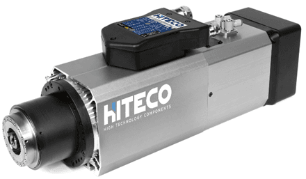
HITECO Electrospindle 14kW - 19 Hp
Vertical electrospindle equipped on a cast aluminum support, sliding on linear recirculating ball bearings (NC managed).
Technical data:
- HSK 63F attachment with double referencing surface to ensure a rigid connection between the tool-holder and the electro spindle itself.
- Electronic rotation control on speed, from 1,500 to 24,000 rpm through static inverter, quick-stop function on rotation standardly equipped.
- Constant power rate (S1/S6) 10/14 kW (13.6/19 HP) from 12,000 to 18,000 rpm
- Programmable left and right rotation
- Inner air blowing system to guarantee a proper fitting with tool-holder.
- Cooling system through forced air ventilation circuit and fan
- Ceramic bearings as support on the main shaft
- Compressed air circuit inside the router cage as prevention against dust pollution
Dust Extraction Outlet for 3-4 Axis Electrospindle
Automatic ON-OFF positioning and manual stroke adjustment on 4 levels.
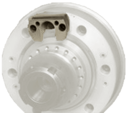
Pre-arrangement for HITECO Aggregates with 1 Pneumatic Outlet
It allows the installation of the angle-driven heads on electrospindle, with HITECO with pneumatic outlet fixed mechanical coupling system for the management of special heads like the floating heads.
Variable Cut-off Behavior for Electrospindle
This novel system is used to adjust the cutting speed of the machine’s electrospindle according to the strain made by the tool on the panel. If the CNC detects an overage due to high load on the electrospindle the system will automatically reduce the feed rate of the axes until the load is restored to within acceptable limits.
Air Blowers on the Electrospindle
Four (4) air blowers capable to convey the chips produced by the cutter during machining. This facilitates the chip ejection.
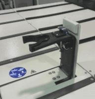
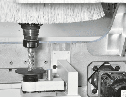
Tool Length Detection Device
This electromechanical device located on the side of the machine frame can detect the tool length through a dedicated software cycle.
The measured length will be sent to the Numerical Control which automatically updates the tool database. This tool database is reviewed by the NC during the loading of any program containing tool compensation into the operator interface.
It is recommended that end users exercise parametric programming to take full advantage of this powerful feature
RO.AX F16V Drilling Head
The drilling unit is equipped with new roto-axial technology, Ro.Ax.
Entirely developed by SCM Group, this project grants:
- Improved cutting quality thanks to the increased rigidity of the spindle (enlarged diameter of the rotating shaft and direct connection, no mechanical interfaces between drilling bit and the shaft itself thanks to Weldon attachment type).
- Increased production rate thanks to a maximum rotation regime up to 8,000 rpm (with optional inverter) which allows a higher penetration speed into the material.
- Reduced maintenance interventions (up to 1,000 hours with lubricating mechanical organs on the unit)
Drilling unit includes:
- Sixteen (16) vertical spindles with independent pneumatic selection
- Bits attachment on vertical and horizontal spindles Ø 10mm, WELDON type (max. length of the bits 70mm)
- Center-to-center step 32 mm between adjacent spindles
- Rotation speed on drilling bits 4,200 rpm (2,500 to 8,000 rpm with optional inverter)
- Driving motor power rate up to 3,9 kW (5,3 HP) – [2,2 kW (3 HP) with 50 Hz frequency]
- 60mm on-off pneumatic stroke on vertical spindles and blade
- Locking system on drilling bit “quarter-lock” type which allows assembling/disassembling tools using single M8 screw and 90° rotation on the wrench.
- Compressed air circuit with high pressure to grant more than 64 kgf thrust on each drilling spindle so to perform operations on the most resistant materials.
Dust Extraction Hood for Drilling Head
Positioned around whole perimeter.
Device to Increase the Drilling Pressure
This device is used for drilling support for the Z-Axis (only on drilling head). It provides Ro.Ax. spindles with an increased thrust during machining, exceeding 64 kg. Each spindle grants full performance on the hardest materials that can be run.
Drilling Unit Managed by Inverter
The inverter managing the rotation speed on the router is also connected to the driving motor on the drilling unit to allow for adjusting the rotation speed of bits up to 8,000 rpm and up to 10,000 rpm on the integrated saw blade.
FAST-12 Twelve (12) Positions Linear Tool Changer (12xx)
Contains a total of 12 positions for HSK tool holders.
The FAST tool changer grants superior performance in tool changing operations. The short distance from the router to the tools, as well as dedicated software optimization, allow for decreased wait time while tool changes are performed.
The FAST-12 is located inside the protective cage on the mobile bridge and can host tools and/or angular heads (please refer to admitted dimensional limits reported in the user manual).
The steel frame construction grants the highest rigidity possible for cases when heavier tools are equipped on it. The tool holder grippers are constructed of a plastic composite material and mounted in an aluminum plate to provide an ideal balance between rigidity and flexibility during tools loading/unloading operations.
The rake and the tool-holders are properly protected against dust by a protective covering over top.
Technical data
- Max. tool diameter: 160mm
- Distance between adjacent positions: min. 125mm
- Max. weight for each tool: 8Kg
- Max. total weight: 42Kg
- Max. weight for each head: 10Kg
Loading Station for FAST Tool Changer
This device - when TRB tool changer is not installed on the machine frame – is used for automatically and easily equipping the FAST tool changer with tools.
It is positioned within the machine frame when not in use
ON-OFF Workpieces Outfeed Pusher
Automatic unloading device which allows the following operations:
- Unloading of the worked pieces on the table side
- Direct positioning on the spoil board
- Spoil board cleaning by means of integrated suction and blower
It consists of a rigid rake (pusher) which touches the spoil board when enabled so to avoid any adjustment once switching to different panel thickness. Additional features:
- Allows the mobile unit to properly push the cut parts – even thin ones – towards the offloading station
- Dust and chips on the spoil board are properly evacuated (best hold down action, no discarded parts, and maximum safety on any successive panel) thanks to the adoption of blowers and a suction hood on the rake itself. The aspiration system is directly connected to the main dust extraction manifold on the machine, avoiding additional tubes on the aspiration system.
The operator gets the best flexibility of usage thanks the ability to associate the outfeed pusher with one of these devices:
- Automatic motorized outfeed belt (optional for a quick panel replacement on the worktable, no operator required to collect the parts during the unloading operation)
- Manual offloading with pushbutton command (optional for a space saving solution, operator required to collect part by part during the unloading operation)
Lower Dust Extraction Grid Between Worktable and Outfeed
Grated stainless steel hood with dedicated connection for suction, able to intercept dust and small chips laying between the processed parts while being offloaded.
Characteristics:
- Exhaust outlet diameter = 200mm
- Exhaust air consumption = 2800 m³/h
- Air speed = 25 m/sec
- Automatic opening valve
- Aspiration tube on bottom position
Control Panel on the Unloading Table
Outfeed table with extension and controls, positioned on the right and left side. The system detects the workpieces by means of photocells to stop the unloading cycle. The processed workpieces can be unloaded through the pressure of the relevant pushbutton.
Side Fences on the Worktable
Fences consist of two (2) pneumatic devices which restrict the ejection of pieces out of the worktable during the automatic offloading phase. This optional is strongly suggested once the machine is equipped as an automated nesting cell. Fences are not suitable to use as front/rear references.
- Fences vertical on-off stroke = 25m
Vacuum Pumps Positioning
Basic machine cell models:
- The vacuum pumps are always located on the base left side, in the area below the unloading belt, even if the belt isn't present
- Basic machine models without automation:
- With 15xx, 18xx, 22xx models and Rotary Vane vacuum pumps it is possible to accommodate up to 2 vacuum pumps below the machine base
- When the Sav€nergy is present, the vacuum pump is always positioned on the base left side
- When the number of pumps exceeds the quantity that can be installed under the base, they will always be positioned outside the base
Two (2) Vacuum Pumps for Total 600 m3/h 60 Hz
The vacuum hold-down system features two (2) 300 cubic meter/hour vacuum pumps. It offers the reliability of a substantial increase in vacuum power and allows the use of spoil boards for nesting full sheets.
Automatic Centralized Lubrication
The correct grease application on the machine’s moving parts is always maintained by means of an electronic control (X-Y-Z axes). The NC managed grease pump ensures that mechanical components on displacement axes (sliding supports, racks, pinions, recirculating ball screw etc.) are properly lubricated according to a pre-programmed interval of time. Standard maintenance operations are allowed with this device.
An alarm signal will be also provided once the pump runs out of lubricant to allow the operator to intervene for a full refill.
Remote Machine Control
This ergonomic device is used by the operator to carry out the main commands of the machine without being tied to the main console. Thanks to this device it is possible to approach the machine and command the main X-Y-Z axes in a semi-automatic modality, enable/disable drilling spindles, set feeding speed, etc.
It’s also very effective for “dry-run” checking machining operations. Use the remote control during simulated cycles so to double check the programming before launching an automatic production cycle.
This ergonomic device is used by the operator to carry out the main commands of the machine without being tied to the main console. Thanks to this device it is possible to approach the machine and command the main X-Y-Z axes in a semi-automatic modality, enable/disable drilling spindles, set feeding speed, etc.
Console with Integrated PC "Eye-M PRO"
The Eye-M PRO is an interface console device connected to the CNC machine which allows the usage of the supplied SCM software. The integrated LED light bar allows the operator to check the state of the machine (emergency, operative, etc.) in real time without the need to be standing directly at the console itself.
It is equipped with an iPC with "fan-less" construction and IP53 grade external protection (IP65 on the front side). This robust solution grants the highest durability even in the worst environmental conditions.
The 21.5" LCD color display, with a 16/9 sized touch screen, allows for an unbeatable easiness and efficiency in controlling the main functions of the machine. Features include:
- Full HD display resolution 1920x1080
- LED lighting
- Multi-touch screen – 10 points of contact
- Wide visual angle 176° Horizontal / 160° Vertical
- "Zero Pixel Defect" quality
- Intel i7 – 2,9-3,8 GHz
- RAM 8GB – DDR4
- Hard Disk: 256GB – SSD
- O.S. Windows Embedded Standard 10 - 64bit
- QWERTY keyboard with English layout
- Wired mouse – 3 functions
- Ethernet port RJ45
- USB port 3.0 protocol supported
Nominal operating temperature: +5°C / +35°C
“S-N-D” 3-Position Selector
Machine dynamic selection when routing and drilling. Through a 3-position selector it is possible to easily change the machine dynamic reaction even when the machine is moving, to immediately adapt to the required use. Placed on the paddle of the machine, it allows the following settings:
Smooth: machine with smoother movements to obtain an impeccable surface finish. Recommended for very delicate materials, it requires significant slowdowns in paths changes.
Normal: ideal compromise between machine reactivity and piece yield. Recommended for most of the machining.
Dynamic: to turn the machine into a plotter. Ideal for routing where speed is essential, such as machining on 3D surfaces.
Technical Specifications
- Send warnings, offering help to eliminate alarms
- Maintenance Support: Maestro-Active notifies the user when maintenance operations need to be carried out on the machine. It also connects the user to the relevant documentation for each procedure.
- User Management and Shifts Management
- Machine Records
- Reporting System: Active can provide the following reports:
- Production Reports
- Alarms
- Events
- Maintenance Reports
Technical Specifications
| Worktable X inside the stop-outside the table | 2517mm (99") |
| Worktable X outside the tabke-outside the table | 2556mm(100") |
| Worktable Y inside the stop-outside the table | 1257mm (49") |
| Worktable Y outside the tabke-outside the table | 1296mm (51") |
| Panel length for alternated work process | 773mm (30") |
| No. of standard stops | 4 |
| Z panel clearance | 150mm – 5,9inch |
| “pro-space” axes vectorial speed | 84m/1' - 275ft/1' |
| “pro-speed” axes vectorial speed | 113m/1' - 370ft/1' |
| Structure Type | mobile gantry |
| X motor power | double on both sides |
| X-Y transmission | rack |
| Vertical spindles | up to 21 – 8.000rpm |
| Horizontal spindles | up to 12 – 8.000rpm |
| Electrospindle Motor Power (S6) 3-4 axes | from 9,5kW to 15kW – 24.000rpm |
| Installed motor power | according to the composition |
| Exhaust outlet diameter | 250mm |
| Exhaust air consumption | 4430m3/h - 25m/s |
| Compressed air pressure | 6,5bar |
| Average compressed air consumption | 400NL/min |
Specifications
| Box Quantity | 1 |